


MRE NX (Mechanically Stabilized Earth)
Web-based design and verification of geosynthetic-reinforced soil structures — generalised Coulomb active thrust and Mononobe-Okabe seismic action, internal pullout and rupture checks on every reinforcement layer, external overturning, sliding and bearing-capacity checks, tieback, compound and global stability, a live 2D section, a 3D model of the structure and a built-in AI assistant. Opens in any browser — no installs, no hardware keys.
What it does
MRE NX takes a reinforced-soil structure from its geometry and soil parameters all the way to a fully verified design — reinforcements, external equilibrium and global stability.
Design and check in a single tool — in Design mode the software computes, layer by layer, the reinforcement length needed to balance the tensile actions; in Check mode the lengths are imposed by the user and the software verifies pullout and rupture at every layer.
Thrust and seismic action — active thrust by the generalised Coulomb method — battered facing, sloping backfill, soil-structure friction — and seismic analysis with Mononobe-Okabe from the kh and kv coefficients. Surcharge on the backfill is diffused with depth by the Boussinesq solution.
Internal checks, layer by layer — tensile action, pullout resistance and rupture resistance of the geosynthetic at every reinforcement level, with the reduction factors for installation damage, durability and creep.
External checks — overturning about the toe, sliding on the foundation plane and bearing capacity of the foundation by the Hansen formula, each returning its own factor of safety net of the partial factors on resistances.
Tieback and compound stability — for battered facings, slip surfaces that intersect the reinforcements, with internal (tieback) and compound stability checks.
Global stability — the simplified Bishop method on circular surfaces, global and compound, with the stabilising contribution of the reinforcements — no separate slope-stability program needed.
Partial factors by code — A/M/R presets for NTC 2018 and Eurocode 7/8, editable by the user; the A2+M2+R2 approach for global stability.
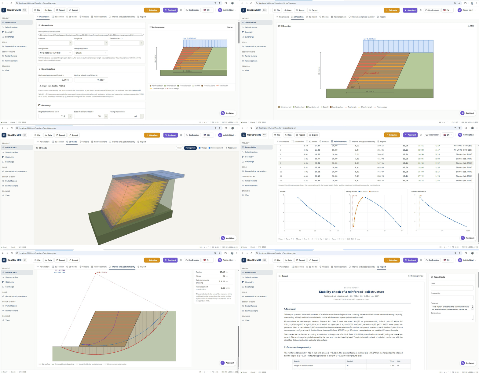
Live 2D section and 3D model — the typical section redraws on every edit — reinforced block, failure wedge, reinforcements with total and effective length shown apart, dimensions and angles — and a 3D model shows the structure along its development, with reinforcement sheets, the active-wedge surface and solid or transparent views.
Reports and cloud projects — a calculation report structured in chapters, exportable to Word and PDF; projects saved in the GeoStru cloud (GeoDropbox), ready-made examples and automatic session save. Interface and report in 7 languages (Italian, English, German, French, Spanish, Romanian, Danish).
Wall or reinforced slope? A distinction few tools make
The inclination of the outer facing changes the nature of the structure — and with it the calculation model that prevails. MRE NX makes the two cases explicit.
Facing close to vertical (steeper than about 70° to the horizontal) — a reinforced-soil wall — the governing concept is thrust: the reinforced volume is a block retaining the soil behind it, the thrust is computed with Coulomb and, under seismic action, with Mononobe-Okabe, and the checks are those of a retaining structure — internal (rupture and pullout of the reinforcements) and external (overturning, sliding, bearing capacity), plus global stability.
Battered facing (flatter than about 70°) — a reinforced slope — the governing concept is that of slip surfaces intersecting the reinforcements: circles inside the reinforced volume that cut through the reinforcement layers, with internal (tieback), compound — surfaces that cross the reinforced volume and exit beyond it — and external/global stability checks, together with rupture and pullout of every intersected reinforcement.
The threshold of about 70° follows the convention of the international guidelines (FHWA, BS 8006). Most software applies a single model to every geometry; MRE NX makes the distinction explicit and adopts the correct set of checks for each case.
The calculation model
Active thrust — Coulomb and Mononobe-Okabe — the static thrust is computed with the generalised Coulomb method; under seismic conditions the inclination of the inertial action θ = arctan[kh/(1−kv)] turns it into Mononobe-Okabe. The design thrust combines the contributions through the partial factors on actions:
S = Sstatic·γG + (Sseismic − Sstatic)·γE + Sq·γQ
The same solution returns the angle of the failure wedge, which bounds the active zone and defines the effective length of the reinforcements.
Internal checks — layer by layer — for each reinforcement level the software computes the tensile action (soil thrust plus surcharge diffusion), the length inside the active wedge and the effective length beyond it, hence the pullout resistance. The design resistance of the geosynthetic accounts for the reduction factors:
Rd = Tult / (RFd · RFid · RFc) FSpullout = Rpullout / Ak FSrupture = Rd / Ak
A reinforcement entirely contained in the failure wedge (Leff = 0) offers no pullout resistance: the 2D section and the 3D model make it immediately visible.
External checks — the block as a retaining structure — the reinforced volume is verified as a rigid body: overturning about the downhill toe, sliding on the foundation plane with soil-foundation friction, bearing capacity with the Hansen formula and the load inclination factors.
Stability — tieback, compound and global with Bishop — the stability of the structure-slope system is analysed with the simplified Bishop method on a circular surface, with the partial factors of the A2+M2+R2 approach of NTC 2018, water table and seismic action included. Tieback surfaces stay inside the reinforced volume and each intersected reinforcement contributes with the tensile force anchored beyond the surface; compound surfaces cross the reinforced volume and exit beyond it, and the reinforcements anchored past the arc contribute a stabilising force limited by the lesser of design resistance and pullout; global surfaces pass entirely below the foundation plane, so the reinforced block weighs on the slices and the reinforcements do not contribute.
How it works
One page, a guided flow through tabs.
1 · Parameters — general data, geometry (H, B, facing and backfill inclinations, foundation depth), surcharge, soils, partial factors by code, seismic coefficients and reinforcements. Every edit updates the preview at once.
2 · 2D section — the dimensioned typical section at full page, exportable to PNG — the same drawing that goes into the report.
3 · 3D model — the structure extruded along its development, with the reinforcement sheets and the active wedge.
4 · Checks — the factors of safety for overturning, sliding and bearing capacity, with the outcome of each check.
5 · Reinforcements — the layer-by-layer table: elevation, tensile action, lengths, resistances and factors of safety.
6 · Internal and global stability — the slip surface over the slices, with the anchored portions of the reinforcements highlighted.
7 · Report — HTML preview and Word/PDF export of the complete calculation report.
What you enter, what you get
What you enter — geometry of the structure — height, base, facing and backfill inclination, depth of the foundation plane; strip surcharge with position and extent; soils — structural fill, retained soil and foundation soil (γ, φ, cohesion), soil-reinforcement and soil-foundation friction; reinforcements — spacing, ultimate strength of the geosynthetic and reduction factors (damage, installation, creep); code and A/M/R partial factors, seismic coefficients kh and kv; slip surface and water table for global stability.
What you get — factors of safety and outcome of every check, with the governing minimum in evidence; the reinforcement table with total and effective lengths, designed or checked; the global stability factor of safety with the geometry of the slices; the drawings — dimensioned 2D section, stability view, 3D model; the Word/PDF calculation report in 7 languages; and the cloud project (.mre) you can reopen from any device.
AI assistant and project tools
Built-in AI assistant — it reads the current project and its results, explains the checks and suggests how to act on the ones that are not satisfied.
Import from a document — attach a report or a document containing the data of the structure and the assistant fills in the form for you.
GeoDropbox — projects live in the GeoStru cloud: save, reopen and share them from any workstation.
Ready-made examples and autosave — sample projects are included so you can start straight away, and the working session is preserved at every edit.
Who it's for
Geotechnical engineers · Designers of retaining structures · Contractors and geosynthetics manufacturers · Public-works technicians · Consultants. MRE NX is built for those who design reinforced-soil walls and slopes today with spreadsheets or desktop tools, and want a single web environment that goes from the geometry to a fully verified, reported structure.
Why it's different
Wall or slope, with the right checks — the distinction between walls (facing close to vertical) and reinforced slopes (battered facing) is explicit, with compound and tieback surfaces inside the reinforced volume where they belong — a distinction few tools make.
In the browser, with no installation — no setup, no hardware key, always up to date.
A validated engine — the calculation kernel is a faithful port of GSRD 1.0 (Geostru Soil Reinforcement Design), verified by an automated test suite against the results of the desktop program.
Global stability built in — simplified Bishop with compound surfaces and the real contribution of the reinforcements, without going through a separate slope-stability program.
2D and 3D in real time — you see the failure wedge and the effective part of every reinforcement while you edit the data.
Professional reports in 7 languages — Word and PDF, with figures and tables consistent with what you see on screen.
Frequently asked questions
How does it relate to MRE desktop?
MRE NX is the web evolution of MRE: the same calculation engine, ported faithfully and validated against the original results, with global stability, a 3D model, an AI assistant, the cloud and a multilingual report on top.
Does it design or only check?
Both. In Design mode it computes the reinforcement lengths required; in Check mode it verifies the lengths you set.
What does a zero effective length on a layer mean?
That reinforcement falls entirely inside the failure wedge and offers no pullout resistance: it has to be made longer. The 2D section and the 3D model show it at a glance.
What is the difference between a global and a compound surface?
A global surface passes below the foundation plane and the reinforcements do not contribute; a compound surface cuts through the reinforced volume, and the reinforcements anchored beyond the surface stabilise the slope. MRE NX admits both and tells them apart, in the interface and in the report.
What is the difference between a reinforced-soil wall and a reinforced slope?
The discriminant is the inclination of the outer facing. With a facing close to vertical the block model governed by thrust prevails (Coulomb / Mononobe-Okabe), with the internal and external checks of a retaining structure; with a battered facing the model of slip surfaces intersecting the reinforcements prevails, with internal (tieback), compound and external/global stability checks.
Which codes are supported?
NTC 2018 and Eurocode 7/8, with editable A/M/R partial-factor presets; the A2+M2+R2 approach for global stability.
Does it handle metallic reinforcements?
No: MRE NX is dedicated to geosynthetic reinforcements (geogrids and geotextiles).
Ready to start with MRE NX?
Choose your plan and start using MRE NX today. Runs in the browser, always up to date, no installation required.